Jump to content United States - English
Hewlett-Packard home Products & Services Support & Drivers Solutions How to Buy
»  Contact HP
Search: (e.g. Deskjet 990cse)


hp.com home

HP and Compaq Desktop PCs -  Motherboard Specifications, P5LP-LE (Emery)


Printable version

»  HP Customer Care

»  HP Pavilion Media Center TV m7480n Desktop PC
» Solve a problem
» Software & Driver downloads
» Setup and install
» How to use
» Product information
» Manuals
» FAQs
» Register your product
» Get e-mail notifications: driver updates & more
» HP Total Care
» Parts ordering
» Repair order status
» Contact HP
Recently Browsed Products
» HP Pavilion Media Center TV m7480n Desktop PC
» HP Pavilion Media Center a1640n Desktop PC
» HP Pavilion Media Center a1613w Desktop PC
Learn more
» Home & Home Office
» Online classes
» Learn and use
» Activity Center
Browse & Buy
» Online store
» Offers & rebates
» Extended service plans
  Help us help you
  This document:
  » Was helpful
  » Was not helpful
  » Does not apply
Content starts here


Motherboard specifications table
Part / Feature Specification / Support
Motherboard description
  • Motherboard manufacturer's name: ASUS P5LP-LE
  • HP/Compaq name: Emery-UL8E
CPU/Processor
  • Socket: 775
  • Supports the following processors:
    • Pentium D 800 series (Smithfield)
    • Pentium 4 600 series (Prescott)
    • Pentium 4 HT (Prescott)
System bus
  • 533 MHz, 800 MHz, 1066 MHz
Chipset
  • Northbridge: Intel 945P
  • Southbridge: Intel ICH7DH
BIOS features
  • 4 Mb FWH EEPROM
  • HP BIOS with enhanced ACPI, DMI, Green, and PnP Features Plus
Form factor
  • Micro-ATX: 9.6 in X 9.6 in
Memory
  • Four 240-pin DDR2 DIMM sockets
  • Supports PC2 3200 (400 MHz), PC 4200 (533 MHz) and PC2 5300 (667 MHz) DDR2 DIMMs
  • Maximum HP/Compaq approved memory is 4 GB*


NOTE: *Actual available memory may be less
Expansion slots
  • Three PCI
  • One PCI Express x16 graphics
Video graphics
  • External only
Serial ATA
  • 4 SATA connectors
  • Each connector supports 1 serial ATA-150 disk drive
Onboard audio or audio card Integrated Intel High Definition (TM) audio (Azalia)
  • Realtek ALC 882 CODEC
  • Supports up to 8 audio channels
  • Dolby Pro Logic IIx compatible
Onboard LAN
  • Intel 82562GT
  • 10/100 Mbps Fast Ethernet
Back panel I/0
  • One PS/2 keyboard port (purple)
  • One PS/2 mouse port (green)
  • One Parallel
  • One IEEE 1394a
  • One RJ-45 networking port
  • Four USB 2.0
  • One coaxial SPDIF in
  • One coaxial SPDIF out
  • Audio ports:
    • line in (light blue)
    • line out (lime)
    • microphone (pink)
    • side speaker out (gray)
    • rear speaker out (black)
    • center/subwoofer (yellow orange)
Internal connectors
  • One floppy connector
  • One IDE connector
  • One 24-pin ATX power connector
  • One 4-pin ATX 12 V power connector
  • Four serial ATA connectors
  • One IEEE 1394a connector
  • Two USB 2.0 connectors
  • One CPU fan connector
  • One PC (chassis) fan connector
  • Two internal audio connectors
  • One front headphone connector
  • One PC panel connector
NOTE: Motherboard specifications are subject to change without notice.
Motherboard layout and photos
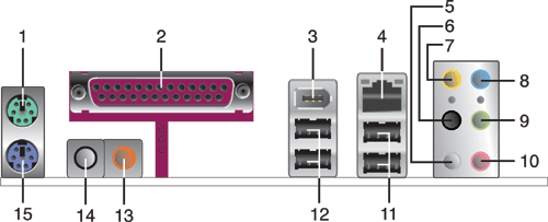
Figure 1: layout
1 - PS/2 mouse port (green). This port is for a PS/2 mouse.
2 - Parallel port. This 25-pin port connects a parallel printer, a scanner, or other devices.
3 - IEEE 1394a port. This 6-pin IEEE 1394a port provides high-speed connectivity for audio/video devices, storage peripherals, PCs, or portable devices.
4 - LAN (RJ-45) port. This port allows connection to a Local Area Network (LAN) through a network hub.
5 - Side Speaker Out port (gray). This port connects to the side speakers in an 8-channel audio configuration.
6 - Rear Speaker Out port (black). This port connects to the rear speakers on a 4-channel, 6-channel, or 8-channel audio configuration.
7 - Center/Subwoofer port (yellow orange). This port connects the center/subwoofer speakers.
8 - Line In port (light blue). This port connects a tape, CD, DVD player or other audio sources.
9 - Line Out port (lime). This port connects a headphone or a speaker. In 4-channel, 6-channel, and 8-channel mode, the function of this port becomes Front Speaker Out.
10 - Microphone port (pink). This port connects a microphone.
11 - USB 2.0 ports 3 and 4. These two 4-pin Universal Serial Bus (USB) ports are available for connecting USB 2.0 devices.
12 - USB 2.0 ports 1 and 2. These two 4-pin Universal Serial Bus (USB) ports are available for connecting USB 2.0 devices.
13 - Coaxial S/PDIF Out port. This port connects an external audio output device via a coaxial S/PDIF cable.
14 - Coaxial S/PDIF In port. This port connects an external audio input device via a coaxial S/PDIF cable.
15 - PS/2 keyboard port (purple). This port is for a PS/2 keyboard.
Clearing BIOS settings
Resetting BIOS settings are done by moving a jumper onto a pair of pins on the motherboard. Use this section to clear settings for the CMOS RAM (sometimes referred to as Real Time Clock or RTC) or the BIOS password.
CAUTION: Do not change any jumper setting while the PC is running. Damage to the motherboard may result.
This motherboard has jumpers to:
  1. Clear the Real Time Clock (RTC) RAM in CMOS. In the default (normal) position the jumper is on pins 2-3.
  2. Disable password checking.
Figure 2: Jumper locations
Clearing CMOS
To clear CMOS, follow these steps:
  1. To clear CMOS settings, temporarily set jumper CLRTC to pins 1-2.
  2. Wait 5-10 seconds and then return the jumper to pins 2-3.
  3. When you startup the PC you will need to enter BIOS setup to reset any custom BIOS settings.
Clearing BIOS password
The BIOS password is used to protect BIOS settings from unwanted changes. If you have forgotten your password you may disable password checking.
To erase the BIOS password follow these steps:
  1. Turn OFF the computer and unplug the power cord.
  2. Locate the jumper labeled CLPWD. The jumper is found at the top edge of the motherboard, near the DIMM sockets. In the default (normal) position the jumper is on pins 2-3.
  3. Move the jumper on jumper CLPWD to pins 1-2 to clear password.
  4. Plug the power cord and turn ON the computer.
  5. Hold down the F1 key during the startup process and enter BIOS setup to change or clear the password.
  6. After changing or clearing the BIOS passwords, remember to reset the jumper to pins 2-3.


Still not finding what you're looking for?


Printable version
Privacy statement Using this site means you agree to its terms Feedback to Webmaster
© 2007 Hewlett-Packard Development Company, L.P.