
Specs
|

|
Starting
This airplane should have only taken a couple of weeks, or months, to build. However, due to circumstances, that I will not bother going into, it has taken me years. No I have not been working on it all that time. That was the problem. I wasn't working on it. But, time has come and I am in the process of finishing it. It will look almost exactly like the Tiger 2 that I had. The one that was victim of my first, and I truely hope last, mid-air.
The main wing, the vertical and horizontal stabilizers are built first. Then you put together the fuselage. That is the point I am at now. I purchased two model mags that had articles on this plane. One of them had warnings about building "errors". I will mention them here in case you got to this page looking for help. Also I will throw in my two cents. Unfortunately, I did not have access to a digital camera as I was building this. So the pics will show some completion ahead of time. However, I think the pics help explain the verbiage and visa versa. You can decide for yourself.
Some tools
As I said, I will be throwing in my two cents on some things. Two tools that I found very useful were a scroll saw and a belt sander. Now then, they are not so important to warrant you running out and purchasing them BUT if they are available they will make your life a lot easier in a couple of areas. And you will need some modeling knives.
The Stabilizers
These are pretty straight forward. Cut position and glue. Not much simpler. The only weird part is the construction of the elevator. Two chunks of balsa joined together by a wooden dowel. But then it is not that bad. Again just some more cutting and gluing. Gets you warmed up for the rest.

The Wing
 Above pic "borrowed/swiped" from Don Wise
so I would have an earlier shot of the wing construction. If you go to his site you will see the construction
of a Tiger 60 Deluxe Kit. It has retracts!!
Above pic "borrowed/swiped" from Don Wise
so I would have an earlier shot of the wing construction. If you go to his site you will see the construction
of a Tiger 60 Deluxe Kit. It has retracts!!
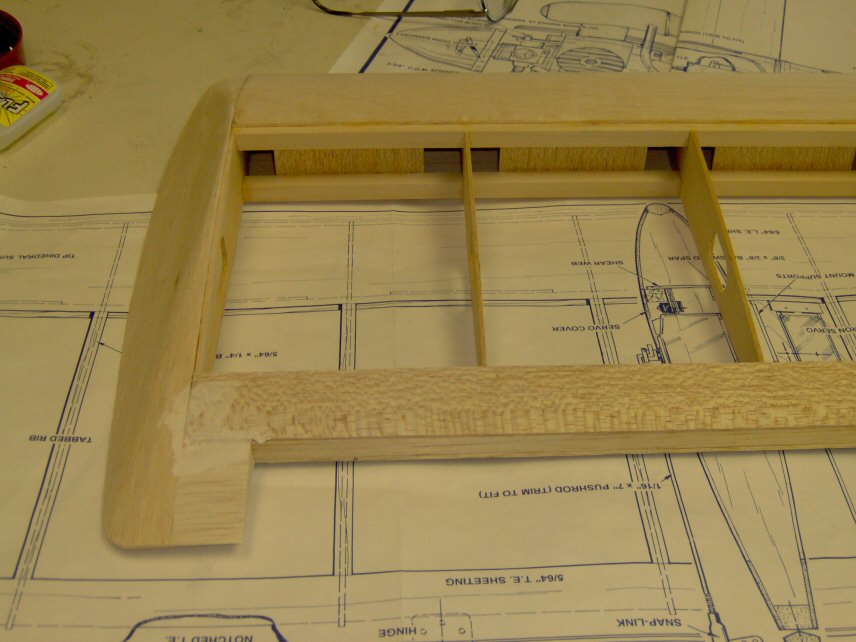
One thing you will notice is that the servos for the aileron are mounted out in the wing halves themselves. I was going to enclose them to make them more professional but forgot and just followed the plans. So I will have servos showing in the completed model... unless I tear apart what I have already built. Don't really want to do that. However, the other thing that they don't mention is, you might want to obtain or make some light tubes for the servo wires. Makes it much easier to get the wires from the receiver to the servos. Both in building and ... ahem... repairs. I used some 24 wt printer paper.

In building, they tell you DO NOT GLUE AT THIS TIME. However, they forget to mention to apply the glue. Through the magazine articles and my trials, I found that glue is needed at step 7 and again at step 8 when building the wing.
The main gear is mounted in the wing. Here again is a suggestion from me. This stems from my experience with the Tiger 2. You might want to beef up the landing gear area so that you won't be putting it thru the wing!! If you always come in for feather lite landings then don't worry about it. Just something to think about as you are building. This is at steps 9, 10 and 11. There is more at step 25.

Now then at step 12 you are to cover the leading edge of the wing with balsa. This is the point where you want to put the tubes for servo wires in ... if you want to. Thinned epoxy should be used to apply the nylon center reinforcing instead of CA as recommended by the instructions.

I'm showing the plywood re-enforcements for the screws ... just because. As usual I had some trouble with getting the holes right. If you follow the plans, you mark and drill the balsa section first. Now they don't say this BUT you might want to check how the screws go in BEFORE you drill and glue the plywood strengtheners on. I had to make corrections to the holes in the balsa so that the screws would go in and out smoothly. Then I drilled the proper size holes in the ply's and aligned them with the wing on the fuse and the screws in. You can put a small amount of thick CA on the ply's and then put the screws through and align them. The thick CA is slow enough that you can do this. If I can do it then anybody should be able to. After the thick CA sets, you can remove the wing and use thin or medium to further secure the ply's ... if you so desire.
Not being much of a wood worker I have been having difficulties in getting a good
finish with my sanding. Hobbico HobbyLite Filler was used to make some areas smoother. The claim that it sands
like balsa is false, in my humble opinion. Believe me, the balsa sands a lot easier... a lot easier. I have
over sanded some areas trying to get them smooth. I've actually made a couple areas worse... I sanded the
trailing edge of the wings tips accidentally a little to thin. This is the area where you add a small piece
of balsa next to the tri-stock used for the wing tips. So be careful with the filler and then with the sanding.
Hmmmmmm.... don't see a really clean way to correct this either.![]()
Speaking of the wing tips, they were an experience in themselves. You are given two pieces of 1-3/4 x 12-3/4 inch tri-stock and then instructed to create wing tips from them. Well, again in my humble opinion, if you don't have some power tools, this is a tuff job. After tacking the tips onto the wing with straight pins, I drew a pattern of the wing on the block. I used a scroll saw and a belt sander to ease this task. I highly recommend that you do not glue the tri-stock to the wing before at least doing some of the cutting and sanding. Use your power sander to get it close, then finish it with a block or other precise hand tool. Naturally the finishing sanding will be after the tips are attached to the wing.
The Fuselage
The main item here to be aware of is the Servo Tray. Do Not put it in when they say to. If you do, you will not be able to drill the wing holes. Which brings up another point. The wing mounting blocks are to be drilled and blind nuts placed in them. Well if you are a little bit off center the blind nut will not allow the wing block to seat properly. Try to get the notched portion of the wing nut to the side that will be close to the fuselage. If not you may have to trim the edge of the slot... on one or both sides.

Another point made in the magazines was the tail. They say place a 1/4" piece of balsa scrap in the tail. It needs to be 3/8" or larger.

I laid the rubber banded fuselage over the plans and everything lined up. However, when I placed a triangle next to the sides, the left side was not straight. The right side was. So, I really didn't have a crooked fuselage like they pictured, but it wasn't totally straight either. Hmmmmm... I decided that it was not enough to make a difference and continued. We'll see.
LATER: I still haven't finished but I do believe that I should have investigated the cocked side on the fuselage. I now have a twisted tail. Don't know yet how it is going to affect the proper alignment of parts. That is to be experienced in a day or two. I did the tragic mistake of getting in a hurry... which is kinda silly since I have had this model for so long.
For what is worth, a tip when mounting the stabilizer: once completely sure it is in the proper position, tips equidistant from the properly mounted wing, I drill two small holes through the stabilizer and the fuselage plate. Then I glue toothpicks into the holes in the fuselage plate. Once I am ready to glue the stabilizer I just apply the epoxy and slide it into the standing toothpicks without worrying that it will move and glue out of alignment. I always use this technique with very good results. (Idea from Albert Providenti )

When doing the above trial fit I did find that one side of my horizontal stab is heavier than the other. I was just setting these items on the fuse and I had to be off center to get the horizontal stab to not fall off!! The vertical stab fits in a slot on the fuse and that helped to lock in both. Not sure why one side of the horizontal stab is heavier. Have to correct that.
The Finishing Touches
Well, not exactly finish, but finishing touches on the construction part. The "actual" finishing touches will be the trim on the covering. But I couldn't think of a better description.
Now then, just what are we "finishing"?? The fuselage and the wing. One of the items is the cornice which helps to blend the fuse into the wing. After being away from this for so long I had to look long and hard for the parts. Then when I found them I was unhappy with the two cornice sides. I thought that they were to thin. So I made some out of a little thicker balsa. In case you missed them, they were shown on page 11 ... when building the wing ... but not used until page 26 when building the cornice.
Now then, I could not for the life of me find the front piece of the cornice. Either, one was not included or I lost it over the years of doing nothing. Don't know how it could have been lost when I haven't even touched the kit. But, I did not find one. So, we have to make our own. The width or length of this front piece will span the width of the cornice top piece. It will be between the side pieces and the wings leading edge. There are some pieces of light ply available that had parts punched out of them. You can use one of these to create this piece. Cut it as wide as the top piece but leave it a lot taller than the area from the leading edge to the bottom of the fuse. Then set it in place and observe. You will see approximately an eighth inch gap on both sides. Mark the center with a pencil and then remove it. Draw lines from the corners to 1/8th inch above the center. Cut these with a scroll saw if you possess one and then sand and fit it to the wing. When you are satisfied, hold it in place and draw a line across it using the bottom as your guide and then cut it down to size. It does of course have to be lower than the bottom so that the top piece will be flush when installed. Be careful on gluing here. We don't want to glue the wing to the fuse. Wax paper makes an excellent inexpensive barrier.
Ooooooppssss.... @#@%&*^%!!! I got out of sequence!! I didn't wrap the center with the nylon fabric. Now then, I can still put the nylon fabric on both sides ... but will that be strong enough??? Guess I need to do some research. Darn!! What is the problem?? I glued the mounting dowel in already.

Well, as you can see above, I have put more of it together for another trial fit. In this case I wanted to check the CG. I'm told that these are tail heavy. Hmmmmm... this particular test did not show that. I need to add more components and the covering but at this point it is more nose heavy than tail heavy. I think that I should mention that the horizonatl tail assembly is thinner. I'll not even go into my mistake or the reason. Just suffice it to say that I had to do a lot of sandin on the horizontal tail assembly and that it is thinner. This may be the reason for my current situation .. or not. At any rate, you might want to check your CG before covering and if it seems to be tail heavy ... thin down the stabilizers. Just make sure that you have the appropriate tools.
Also you might notice that I have a big engine up front. It is a brand new Super Tiger 75. A Tiger powering a Tiger.
The Controls
Now, I'm sure that when this plane was designed that the bass wood controls were probably a good idea. And to some they are probably still a good idea. But to me they are not. I can't seem to get them to fit in there correctly and I'm not sure how we are gona get the bass wood rod assemblies in once this thing is covered anyway. Course I'm not sure how we are going to get any assembly in after it is covered. There have been many "new" ways of doing things fabricated since this original design and I thing that I am going to use one of the newer control assemblies.
Well, as you can see below, I used Su-Pr-Rods for the controls. I atempted to bass wood controls but did not like them. So I went plastic/nylon. They are flexible yet stiff enough to contol the plane when properly installed. you have to look closely but you will see the elevator and rudder controls in a piece I made to hold them. For these flex things you do have to secure the ends ... at least one of them. For the elevator and rudder I secured both ends. On the steering and engine only one end.
Also notice the silver line that looks like a wire. It is a thin piece of tubing which will hold the radio antenna. Pretty slick idea. I never thought of that before.

The colors are "Winston" colors. Metalic Red, White and Gold. I used to partake of the pleasure but had to quit because of health and the Lord. You can't be a very good witness for the Lord and smoke. On top of that I had a heart attack. So I took it as a message from the Lord ... quit!! But I still like their colors. That was the scheme that I used on the Tiger II that I had and this one was to replace it.
The horizontal stab bottom, elevator, rudder, bottom fuse nose, alerons and the bottom of the main wing were done in white first. Wanted to do all white before any other color. You always put the lighter colors first and then the darker ones on top.
I was going to run some string thru the tubes so that I could pull the servo wires thru after the covering was ironed on. But after doing the bottom it dawned on me ... duhhhh ... put the servos in now and then cover the top!! So that is what I did. Even at that brilliance I had a problem. When I cut out the section for the wires to come thru and then pulled them up, one side was cut. Now I'll swear that I didn't cut them but then I didn't notice them being cut before hand. Anywhoo .. I went to the local hobby shop and purchased two more. I got two so that I could attach both on the end, pull the wires thru and remove the bad one, attach the new one and then pull them back. So I now an extra good one and an extra bad one. These can be used in any future repairs ... if needed ... and I hope not.


Now we have the cockpit which contains a dash panel. There is a peal and stick which is black with what looks like white instruments. However, the dials are clear. The white comes from the peal and stick backing. So, we put some white mono-coate on the dash. Then when we put the dash sticker on it will look ok.


Now we have all the parts ... the top ...

... and the bottom.

I at first tapped up the servo extention and then later I decided that I had better replace it. I don't want to loose this plane over a 2 or 3 dollar part.
Now we get to put the tail assembley on. First the horizontal stab. Notice that the mono-coate is cut away where the glue will go. The toothpic idea was mentined above. Don't think that I did it the way he was talking about but I got the stab in proper position early on with the pics and then used them for positioning thereafter. I didn't drill holes for the vertical cause I couldn't figure out how to make sure they were straight. I didn't have the proper equipment to brace the vertical stab and then drill straight holes. So it will be mounted and held with a right triangle device to keep it straight.


I have never covered and then glued these parts, the horizontal and vertical stabs, on before. I wasn't confident enough to use CA and I'm not sure on the epoxy mix. I didn't want to use to much but later I'm afraid that either the glue is to old or I didn't mix enough. It's tuff being limited in funds on these things. I don't know, does epoxy go bad with age??
Flex Controls
I used the flexible controls, which I think I might have mentioned earlier. But anyway, I had the part that controls the Elevator and Rudder to long at the exit. I also had some problems with the throttle and the nose gear. For the tail controls I used a longer wire at the exit. for the Throttle and Nose gear I put in some extra braces. After these problems, which I encountered after covering, I'm not so confident in how I set up the tail controls. I'm not gona rip it apart to change anything. I have operated the controls and tried to force them back and they resist enough to make me think they will be ok. If not, then it will kiss the desert!!
 This is a view of the straight flex exit. Notice the wire rod portion is small.
 This view shows the re-do of the controls at exit. Notice the longer wire rod.
 The Throttle needs more work. I would like to have mounted the servo the other way BUT I could not. The pre-defined
servo plate was already glued in AND was to close to the fuselage side. This prevented mounting the servo the other
way due to the servo wires. I tried and tried but could not get a servo to fit the other way!! I will probably put in
a longer formed wire to get more control. The control that is lacking is the minute trim movements. They don't really
take hold till you move the throttle control and then bring it back. Not the proper way to do things.
The Throttle needs more work. I would like to have mounted the servo the other way BUT I could not. The pre-defined
servo plate was already glued in AND was to close to the fuselage side. This prevented mounting the servo the other
way due to the servo wires. I tried and tried but could not get a servo to fit the other way!! I will probably put in
a longer formed wire to get more control. The control that is lacking is the minute trim movements. They don't really
take hold till you move the throttle control and then bring it back. Not the proper way to do things.
Finished Product


The switch is close to the canopy. I'm lucky that the later item fits. I am also lucky that the switch fits. I
placed the pattern on the outside, marked where to cut and drill and did it. Never gave a thought to the full
size of the switch or to the canopy. Fortunately the Lord was watching over me. The switch just fit and so did
the canopy. Course as it turns out, the switch could have been a little farther back. But sometimes we learn, or
remember, to late.


My neighbor was kind enough to hold the plane so I could show the bottom.

ARRRRGGGG!!!!
If you look above you will see that I used some flex rods to setup my controls. The appearance of being ok was misleading. It flew and looked great. Then I heard a buzz ... but didn't recognise what it was at first. Second time around my brain started analysing ... flutter .?. but to late. The Horizontal stab broke off and fluttered to the ground. Shock and Awe!! I stood there with my poor reactions and did not kill the engine. I can't remember if I even tried to pull up. It was in a shallow dive. Before I could come to my senses ... It kissed the desert!!
In pieces ....

The stab broke off in the air .... elevator flutter. But it broke on the side without the horn.
Could I have saved it if I had reacted properly??? I'll never know cause I don't want to repeat the situation.

... I did seal the hinge gaps ..?? .. if you look closely, you will see the clear
monocote over the gaps ... but alas the controls were to sloppy.

A good write-up that I found on Flutter ... unfortunately AFTER the crash.
Quicker Build??
Well, thanks to one of my daughters, the eldest, I got a replacement for the crashed Tiger. This time I won't have
as much tedious work to do. It was a wonderful Christmas present...a Tiger 60 ARF. Unfortunately, I had a heart attack and a sextuple
bypass December 1st, 2006. I wasn't allowed to do much for a few months. So we get a slow build again.

(Notice the club in the background?? That is one of my other hobbies. Also helps with the cardiac recooperation.![]() )
)


Now as you can see above, this thing is mostly together. That is good and bad. The good part is that I won't have to mess with all that. The bad part is ... I made some mods to strengthen certain areas and these are now covered up. Hmmmmm.... what to do?? Well, let's see what they did first.
Examining the ARF
In the Kit version the first thing they had you do was build the horizontal and vertical stablizers.
Since those are already built ... we won't have to. Instead, they have you mounting the ailerons to the main wings. Which brought
about a bad surprise. The left wing was done first, not necessarily by any choice, it just happened to be the first one that I
grabbed. Getting those blankety, blank Jet hinges in those slots is a challenge. I haven't used them before but I decided to go
along with what was supplied. After a longer than I wanted struggle with those hinges... and succeeding, I moved on to the right
wing. This is where the bad surprise came in. I have two broken ribs in the right wing. At least two that I can see. One on each
side of the opening for the aileron servo.

^ Notice on the one above there is an obvious gap. This is the one that had the loose piece that caught my eye. ^

^ On the above you have to look close but you can see two cracks about a 1/4" or more apart. Below the black dowel. ^
^ Actually it was technically above the dowel, cause we are looking in from the bottom of the wing.
![]() ^
^

^ Now then, I took the wing outside and used the sunshine to show the crack better. Under/over the dowel. ^
Calls and checks were made... both to the Hobby shop where it was purchased and to Carl Goldberg. I got it for Christmas and the warranty is for 30 days. Also ALL warranties are off once construction has been started. Hmmmmmm... not very fair. But then..... oh well.
Soooooo, what are we gona do about this. Well, they build ships in bottles don't they..? I should be able to strengthen those two ribs and then hope for the best. I am trying to avoid cutting the wing up. I took it to my Saturday coffee run with my flying buddy, Danny. He looked at it, took hold of it and twisted it and said, "It looks strong to me". That's somewhat what I was thinking. However, a little strengthening would be better ... right??
Benefits of previously building a kit
I have the plans. I made a pattern of the ribs on a piece of paper. Cut the paper out and then placed it on a
piece of balsa wood. Traced it, cut it and then placed the piece over the cracks and glued it in with medium ca. Then used some thin ca
to strengthen the patch. Maybe it isn't the greatest but it is better than nothing. Annnddd... I don't have to cut it apart and rebuild it.


^ In the two pics above you can see my patches. ^
???